Here is an interesting theory about the construction of Stonehenge. Makes a lot of sense to me.
Showing posts with label tools. Show all posts
Showing posts with label tools. Show all posts
Wednesday, May 09, 2007
Friday, March 30, 2007
Studley by name, Studley by nature
Back in the mid 90s, I remember picking up a magazine at the military dentist. Airforce magazine or flight international or something like that. Inside was a picture I stared and stared at. It was an advertisement for something, I can't remember what - but I never forgot the image.
It's been well over 10 years and I was chatting to my mate Irish Stu about this tool chest I once saw, and how impressive it was.
Well, after describing it to Stu, I figured I do my darndest to find it on the web.
Using image google, I was surprised to find it within minutes.....so here it is:
 The Studley Tool Chest
Fine Woodworking Magazine Article (incl High Res downloads)


Monday, December 04, 2006
Buy a DIY Aircraft online
I had to share this. In my view, the internet has come of age when I can go and add a kitset Aircraft (yes a real aircraft) to a web shopping cart, and pay for it with my Visa.
DIY + Aircraft + Internet + VISA = one helluva busy garage.
Indeed, for those of you who know me, we have found a match.
http://hummelbird.com/#UC
is the site of a small DIY aircraft company in a place called Bryan, Ohio. I'd like to go to a place called Bryan. Bryan is also a brilliant name for a cat don't you think?
Personally, I think if I was going to build an DIY Aircraft, I would go for a Van's RV. I just like the look more and there are a lot of them around.
Both the Van's RV and the Hummel Ultra Cruiser look to be similar construction, predominantly using Aluminium Alloy which is something I personally prefer over GRP (resins & fibreglass n shit like that) as it's more retro. Besides that, I have the tools already.
http://www.vansaircraft.com/
The Vans RV-10 is a sleek 4 person aircraft, so it's in a different league in my opinion.
Anyway, there goes ANOTHER thing to add to the list of things to do. Just incase I ever get bored.
DIY + Aircraft + Internet + VISA = one helluva busy garage.
Indeed, for those of you who know me, we have found a match.
http://hummelbird.com/#UC
is the site of a small DIY aircraft company in a place called Bryan, Ohio.
 I'd like to go to a place called Bryan. Bryan is also a brilliant name for a cat don't you think?
Personally, I think if I was going to build an DIY Aircraft, I would go for a Van's RV. I just like the look more and there are a lot of them around.
Both the Van's RV and the Hummel Ultra Cruiser look to be similar construction, predominantly using Aluminium Alloy which is something I personally prefer over GRP (resins & fibreglass n shit like that) as it's more retro. Besides that, I have the tools already.
http://www.vansaircraft.com/

The Vans RV-10 is a sleek 4 person aircraft, so it's in a different league in my opinion.
Anyway, there goes ANOTHER thing to add to the list of things to do. Just incase I ever get bored.
Wednesday, November 08, 2006
Best Inventions of 2006
I have been incredibly busy lately, so apologies for not blogging. (well actually I haven't been that busy, but ya know how sometimes you look at the calendar and realise it's a month later than you thought?)
Here is a pretty interesting read:
http://www.time.com/time/2006/techguide/bestinventions/
Here is a pretty interesting read:
http://www.time.com/time/2006/techguide/bestinventions/

Friday, September 29, 2006
Sir Frank would be impressed
Sir Frank Whittle invented the Jet Engine in the 1930s. 
As part of my engineering training in the RNZAF, I spent many hours studying how jet engines and the components that hang off them work, including rebuilding a jet engine to pass the course.
When I was working as a Aircraft Technician specializing in A4 Skyhawks, I was lucky enough to be a high power Jet Engine tester, which meant it was one of my jobs to sit in the cockpit of the recently serviced Fighter Jet and take the engine thru a test routine, which included going over 100% throttle while the jet was held back by a single (but big) chain. Slamming the throttle as fast as possible to test spool times was something I had to do - can you imagine that? It's really a difficult thing to describe, but sitting perhaps 2 meters in front of a Jet engine that is making a noise that can be best described as TERRIFYING HOWLING is extremely noisy, scary, exhilerating if not down right stupid...It sure gives some sense of importance in needing to put it together right.
Watching a jet go past in the sky is one thing, but try standing beside a jet at full noise and see what it is like. Now sit IN it......crazy.
I still think of my time working on A4s as a career highlight. That was a time I bolted out of bed to go play....er.... I mean work.
Check out this ( from the BBC)
Link to BBC Story
Wiki about that 'Whittle' guy
Wiki about the A4 Skyhawk
Royal New Zealand Air Force
ATSI, Arizona

As part of my engineering training in the RNZAF, I spent many hours studying how jet engines and the components that hang off them work, including rebuilding a jet engine to pass the course.
When I was working as a Aircraft Technician specializing in A4 Skyhawks, I was lucky enough to be a high power Jet Engine tester, which meant it was one of my jobs to sit in the cockpit of the recently serviced Fighter Jet and take the engine thru a test routine, which included going over 100% throttle while the jet was held back by a single (but big) chain. Slamming the throttle as fast as possible to test spool times was something I had to do - can you imagine that? It's really a difficult thing to describe, but sitting perhaps 2 meters in front of a Jet engine that is making a noise that can be best described as
 TERRIFYING HOWLING is extremely noisy, scary, exhilerating if not down right stupid...It sure gives some sense of importance in needing to put it together right.
Watching a jet go past in the sky is one thing, but try standing beside a jet at full noise and see what it is like. Now sit IN it......crazy.
I still think of my time working on A4s as a career highlight. That was a time I bolted out of bed to go play....er.... I mean work.
Check out this ( from the BBC)
Engine on a chip drives laptops
It is one of the most hotly contested and closely watched areas of research - how to provide the most efficient energy source for the mobile devices we carry with us.
 Each component is made on silicon wafers
Batteries and fuel cells are established contenders to power laptops and mobile phones, but now researchers at the Massachusetts Institute of Technology (MIT) have come up with a novel approach to the power conundrum - by building an engine on a chip.
Gas-turbine engines more normally power whole cities but MIT's Professor Alan Epstein was determined that miniscule versions could be used to "power a person".
Ten years on from having the brainwave, Professor Epstein believes the microengine could give batteries a run for their money, offering 10 times the power of a battery of the same weight at the same price point.
"A laptop that will run for three hours on battery charge will run for 15 to 20 years using the microengine and it should end up costing no more than current batteries," said Professor Epstein.
He believes it could be available commercially within three to five years.
Tiny scale
It has been a long road for Professor Epstein and his team of 50 other staff and students.
"When I first told people that I wanted to build a gas-turbine the size of a 50p piece they fell off their chairs laughing," he told the BBC News website.
But with the experts needed to make his vision a reality just a stone's throw from his office at MIT, it didn't take long to persuade them that he wasn't joking.
"A few days later they would call back with a way to do things and then they were hooked," he said.
So how exactly does one set about making a tiny fuel-burning engine? A compressor, a combustion chamber and a spinning turbine are all essential parts but obviously cannot be made in the conventional way on such a tiny scale.
So the team had to use etched silicon. The resulting microengine is made up of six silicon wafers piled on top of each other and bonded together.
To bring down costs, up to 100 components are made on one large wafer and cut into individual units.
The process begins with a tiny combustion chamber where fuel and air mix and burn at the melting point of steel. Turbine blades spin at 20,000 revolutions per second - 100 times faster than those in jet engines.
Fun process
 The finished microengine fits in Prof Epstein's palm
A mini-generator produces 10 watts of power and a tiny compressor raises the pressure of air in preparation for combustion. The cooling process is managed by sending the compression air around the outside of the combustor.
Separately it has been proved that all the parts work so the challenge now is to test an integrated chip.
According to Professor Epstein, this should be done by the end of this year but it won't be easy.
Each microengine will be on a single piece of silicon so there is no margin for error. One tiny mistake in a single component would mean starting from scratch, and if anything needs to be changed, the whole design process would be back to the drawing board.
The journey so far has been "an astonishing amount of fun", said Professor Epstein, although, as with many projects, threw up surprising problems.
"What we thought was going to be hard, wasn't, and the things we hadn't thought about were the biggest problems," he told the BBC News website.
"We thought the combustor would be one of the hardest things but in fact it turned out to be the manufacturing of the bearings that was more difficult," he said.
Steam-powered laptops?
While Professor Epstein has lived and breathed his project for the last 10 years, he is aware that there is plenty of competition around.
Batteries are improving all the time, while announcements about advances in fuel-cell technology are regular and closer to commercial reality.
What technique wins out will ultimately be down to what consumers find most satisfactory.
"The users don't care about what powers their laptop. Whether it is chemistry or thermodynamics is a mere detail," he said.
The idea of engine-powered laptops may seem outlandish but research is ongoing to put other types of engine on chips, according to Professor Epstein.
As well as millimetre-scale combustion engines, there is also the possibility of laptops powered by steam engine - which would perhaps be the ultimate collision between old and new technologies.
Link to BBC Story
Wiki about that 'Whittle' guy
Wiki about the A4 Skyhawk
Royal New Zealand Air Force
ATSI, Arizona
Friday, September 22, 2006
Making a watch by hand
Here is a "how to" on designing your own watch and making it. Handy. Very handy. http://web.ticino.com/dcorson/watch/index.html
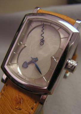 http://web.ticino.com/dcorson/watch/index.html
Saturday, September 16, 2006
DIY Wind Generator
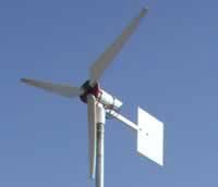
I'd really like to make one of this next weekend. Seriously.
We have a 2m x 4m balcony, so I reckon I could do it. Better not, Jack likes to hang out there so if there are blades out there chopping in the wind - well, it might end in tears. Maybe up on the roof of the building....hmmm.
From the instructables website...
Chispito Wind GeneratorThe Chispito Wind Generator was designed to be simple and efficient with fast and easy construction. There are no limits to what you can do with wind power. There is nothing more rewarding and empowering than making a wind powered generator from scrap materials. Most of the tools and materials in this manual can be found in your local hardware shop or junk pile.
Chispito Wind Generator
A really good NZ article about converting washing machines into Wind Generators
Another excellent wind generator site
Sunday, August 06, 2006
Make an iPod power pack for $7USD
You may have noticed my earlier post with a link to making your own iPod power pack.I can't help thinking it was pretty complex and while it is small, how long would it charge for?
I thought I would put my money where my mouth is and have a go and making one based on something I thought up myself and as I so willingly suggested to a poster on forumosa.com who was looking for an iPod power pack.
The basic theory was to get a Car accessory -USB adaptor, and rip it to bits, combine it with some batteries and presto, have a power pack to charge an iPod away from any usual power source.
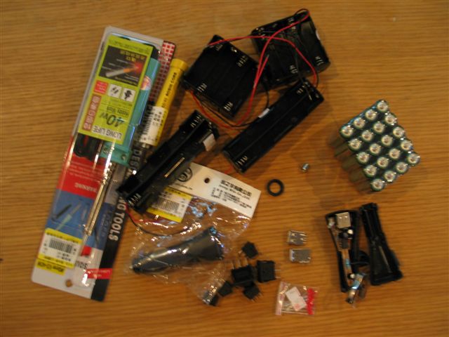
So I went to Guang Hua Computer Market today and picked up some bits. As you will see in the photo, I got carried away with various shaped battery holders and cases, and different switches, just to make sure I had all options covered. Here is a photo of everything that I bought, including a soldering iron (80nt - and that wasn't the cheapest!)

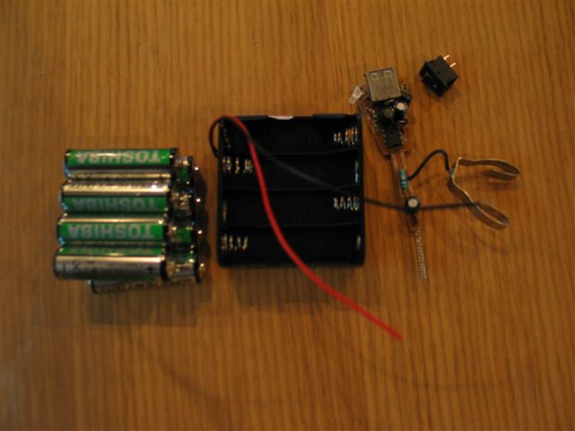
Here is a photo of the bare minimum bits you'd need based on a 12v DC input (8 x 1.5 AAs - but you will see I used a different configuration to this)
The final parts list (that I used) is as follows:
1 x Car Accessory-USB adaptor = 90nt
2 x 8AA battery holders = 40nt
1 x rocker switch = 12nt
16 x AA heavy duty batteries = 79nt
1 x Black plastic project case = 80nt
total price = 301nt (including batteries)
total price = 222nt (unit only) About $7 USD!!

First step was to take the Car Adaptor to bits. A blade screwdriver in the seam and it was in bits.
A small sticker on the adaptor stated:
Input: DC 12V-24V Output: DC 5.0V +- 5% Max: 500mA
Wha,wha....what? This handles 24V input? So, after thinking about this for 2 seconds, I figured 16 AAs would be better than 8. Will last longer. :)
After a bit of jiggling around I found that I had to use the 2 long battery holders instead of the 2 flat ones.
I had bought a new LED so I could have a power indicator, as I presumed the one on the adaptor would be in the wrong position. After some testing, I discovered the adaptor LED was a hi-tech 2 color unit that indicated green for 'ready' (input ok) and red for 'charging'. I desperately wanted to keep this feature, so I carefully bent the LED around so it would sit in a hole beside the USB slot in the case.
Next step was to cut the holes for the USB slot, LED and the rock switch.
I positioned these all at one end, using the space not occupied by the battery holders
I used a drill to make some holes which I finished off with a craft knife and needle file. That took the longest time, about an hour for a decent job.
Then it was just a matter of assembling the switch and USB unit, with attached LED into the case. Due to precision hole making, these were a nice push fit.
Then it was a matter of soldering the wires from the battery holders to each other (+tve to -tve) and one to the USB unit, one to the switch, and one between the switch and the USB unit.
I should mention at this point that some web research outlined that the center pin part of those adaptors is +tve.
I melted a bit of excess plastic with the soldering iron to anchor the other end of the USB unit to the case.
Some tape tidied the only wire-to-wire soldering and it was ready for business. I packed out the battery to case void with some polystyrene wedges to stop it all rattling around.
As you can see, it works a treat and it actually looks quite professional too...
The rest of the Photos show: Before the lid goes on.
With the lid on, charging iPod.Red LED indlicates charging.
The complete unit is a reasonable size, but with 24V on board, I am hoping it would be good for a few charges.
Conclusion:
220nt for a battery pack for any USB charged device is pretty cheap.
A couple of hours to make it, and I am not into electronics (no kidding, I had to even buy an iron).
Well worth the effort I reckon.
 If you were a real geek:
You could put in a external DC input, and a charging circuit. Then you could use rechargable batteries which would save money in the long run, but I figure I wont actually use this unit more than a few times a year MAX so I'll just stick with 80nt worth of once-use batteries.
Some things I'd like to know though....
What sort of safety features would be good to put in there (i.e. a fuse)?
How long will 24VDC for 16 x 1.5v AAs provide charge at 5VDC 500mA max?
What about heat?
Disclaimer: I just built this to see if it could be done, I haven't tested it in any way, so if you want to make one, do so bearing this in mind...
I thought I would put my money where my mouth is and have a go and making one based on something I thought up myself and as I so willingly suggested to a poster on forumosa.com who was looking for an iPod power pack.
The basic theory was to get a Car accessory -USB adaptor, and rip it to bits, combine it with some batteries and presto, have a power pack to charge an iPod away from any usual power source.
So I went to Guang Hua Computer Market today and picked up some bits. As you will see in the photo, I got carried away with various shaped battery holders and cases, and different switches, just to make sure I had all options covered. Here is a photo of everything that I bought, including a soldering iron (80nt - and that wasn't the cheapest!)
Here is a photo of the bare minimum bits you'd need based on a 12v DC input (8 x 1.5 AAs - but you will see I used a different configuration to this)
The final parts list (that I used) is as follows:
1 x Car Accessory-USB adaptor = 90nt
2 x 8AA battery holders = 40nt
1 x rocker switch = 12nt
16 x AA heavy duty batteries = 79nt
1 x Black plastic project case = 80nt
total price = 301nt (including batteries)
total price = 222nt (unit only) About $7 USD!!

First step was to take the Car Adaptor to bits. A blade screwdriver in the seam and it was in bits.
A small sticker on the adaptor stated:
Input: DC 12V-24V Output: DC 5.0V +- 5% Max: 500mA
Wha,wha....what? This handles 24V input? So, after thinking about this for 2 seconds, I figured 16 AAs would be better than 8. Will last longer. :)
After a bit of jiggling around I found that I had to use the 2 long battery holders instead of the 2 flat ones.
I had bought a new LED so I could have a power indicator,
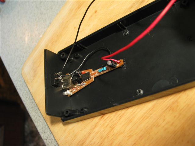 as I presumed the one on the adaptor would be in the wrong position. After some testing, I discovered the adaptor LED was a hi-tech 2 color unit that indicated green for 'ready' (input ok) and red for 'charging'. I desperately wanted to keep this feature, so I carefully bent the LED around so it would sit in a hole beside the USB slot in the case.
Next step was to cut the holes for the USB slot, LED and the rock switch.
I positioned these all at one end, using the space not occupied by the battery holders
I used a
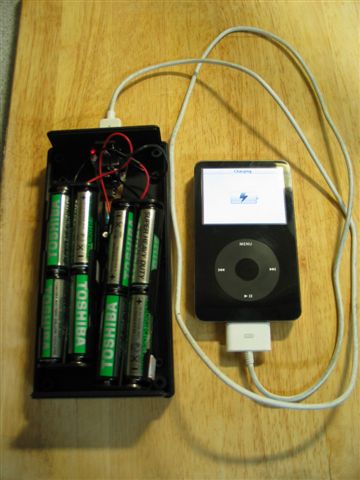 drill to make some holes which I finished off with a craft knife and needle file. That took the longest time, about an hour for a decent job.
Then it was just a matter of assembling the switch and USB unit, with attached LED into the case. Due to precision hole making, these were a nice push fit.
Then it was a matter of soldering the wires from the battery holders to each other (+tve to -tve) and one to the USB unit, one to the switch, and one between the switch and the USB unit.
I should mention at this point that some web research outlined that the center pin part of those adaptors is +tve.
I melted a bit of excess plastic with the soldering iron to anchor the other end of the USB unit to the case.
Some tape tidied the only wire-to-wire soldering and it was ready for business. I packed out the battery to case void with some polystyrene wedges to stop it all rattling around.
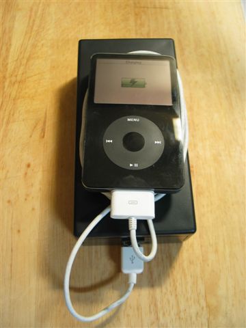
As you can see, it works a treat and it actually looks quite professional too...
The rest of the Photos show: Before the lid goes on.
With the lid on, charging iPod.Red LED indlicates charging.
The complete unit is a reasonable size, but with 24V on board, I am hoping it would be good for a few charges.
Conclusion:
220nt for a battery pack for any USB charged device is pretty cheap.
A couple of hours to make it, and I am not into electronics (no kidding, I had to even buy an iron).
Well worth the effort I reckon.
 If you were a real geek:
You could put in a external DC input, and a charging circuit. Then you could use rechargable batteries which would save money in the long run, but I figure I wont actually use this unit more than a few times a year MAX so I'll just stick with 80nt worth of once-use batteries.
Some things I'd like to know though....
What sort of safety features would be good to put in there
 (i.e. a fuse)?
How long will 24VDC for 16 x 1.5v AAs provide charge at 5VDC 500mA max?
What about heat?
Disclaimer: I just built this to see if it could be done, I haven't tested it in any way, so if you want to make one, do so bearing this in mind...
Wednesday, July 05, 2006
Traditional Wood Fired Pizza Oven
I think I have mentioned before that not having a garage in Taiwan is driving me crazy....but it's bigger than that. I mean, what do I want a garage for? To build shit, that's what.
Recently my Mum (That's Mom to those from North America) sent me a copy of a fine article out of a NZ magazine called "The Shed". The article is a step-by-step thing on how to build your own Traditional outdoor oven.
I could scan in in for you, but it's just too hard. Instead I found a pretty good site on it.
Here is one that I reckon looks cool:
More pics here
I'd actually forgotten about these things until recently, but when we were travelling around Italy in 2002, these ovens are actually the 'normal' way of cooking pizza, although usually they are built indoors. I found it fascinating to watch the doods making the dough, then turning it into Pizzas for cooking right there in the restaurant.
At the time I was thinking this would be a good addition to Truantville. I like the idea of (wait for it....the Binford idea) making a combo style, that includes a BBQ, or one that is built into a wall of the house and can be used from either inside or outside. I haven't seen that done yet, but I am sure that would be the best way to do it to avoid freezing yer ass off in the winter, or being forced to cook inside while yer mates are outside boozing on the deck in the sun. I reckon it would be great to invite people over and have them cook their own pizza, just the way they like it.
Anyway, I reckon this will be one of the FIRST things to be built on Truantville. Even if it's all there is, it gives food, warmth and a social focus....and let's face it, that's what a good home is all about right?
http://www.traditionaloven.com
Recently my Mum (That's Mom to those from North America) sent me a copy of a fine article out of a NZ magazine called "The Shed". The article is a step-by-step thing on how to build your own Traditional outdoor oven.
I could scan in in for you, but it's just too hard. Instead I found a pretty good site on it.

Here is one that I reckon looks cool:
More pics here
I'd actually forgotten about these things until recently, but when we were travelling around Italy in 2002, these ovens are actually the 'normal' way of cooking pizza, although usually they are built indoors. I found it fascinating to
 watch the doods making the dough, then turning it into Pizzas for cooking right there in the restaurant.
At the time I was thinking this would be a good addition to Truantville. I like the idea of (wait for it....the Binford idea) making a combo style, that includes a BBQ, or one that is built into a wall of the house and can be used from either inside or outside. I haven't seen that done yet, but I am sure that would be the best way to do it to avoid freezing yer ass off in the winter, or being forced to cook inside while yer mates are outside boozing on the deck in the sun. I reckon it would be great to invite people over and have them cook their own pizza, just the way they like it.
Anyway, I reckon this will be one of the FIRST things to be built on Truantville. Even if it's all there is, it gives food, warmth and a social focus....and let's face it, that's what a good home is all about right?
http://www.traditionaloven.com
Tuesday, July 04, 2006
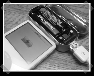
Make your own battery powered iPod charger
I have seen 1 or 2 'powerbricks' around. They are basically a big battery pack that allow you to charge up or run another device, like an iPod, Pocket PC, digital camera or whatever in situations where you normally don't have easy access to 110/240v - such as a Camel Caravan in the Sahara or on a long-haul aircraft flight. The problem with these commercially available things is they are freakishly expensive.
Wednesday, May 10, 2006
Make a Dog Catching Pole
I have made few of these for AnimalsTaiwan.org mainly because they are not readily available in Taiwan, but also, the commercial poles in the US run towards $100+ USD. The pole shown here costs approx $200nt (about $6-7USD) and half an hour or so to make. This pole is not as good as a commercial pole, but is ideal for voluntary organizations or for people who just need to use one occasionally.
Guidlines about humane animal handling
Tomahawk Control Poles
Ketch-All animal control equipment
Alana Ecology Control Poles
The most difficult part to find is plastic coated cable. Dogs will bite the loop, so plastic coax or similar is not strong enough. Some alternatives for sourcing the cable are cable based plastic covered clothes line, and long bicycle cable locks.
I was recently in Canada on business and found some 3/16” plastic coated aircraft cable at a Home Depot for 36 cents CND a foot.
What you need: (prices quoted in Taiwan Dollars. 30nt = 1 USD)
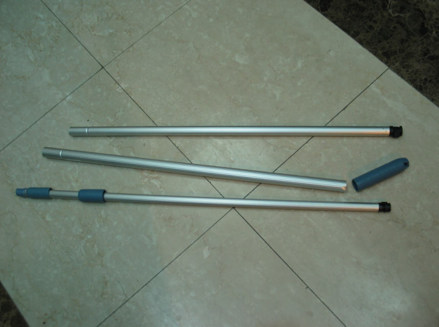
- 1 standard extendable mop/broom utility pole ($85nt)
- 10ft plastic coated steel cable (approx 100nt)
- 2 Hose Clips ($35nt for 4)
- 2 Metal Squash type Cable clips/clamps (5 nt or so) or a few plastic cable ties.
- 1 Roll of Electrical Tape (10nt)
Tools:
- 1 Electric or hand drill
- 1 3/16” or ¼” drill bit (slightly bigger than the cable)
- 1 Pair of pliers
- 1 Screwdriver
- 1 Dog (for testing purposes)

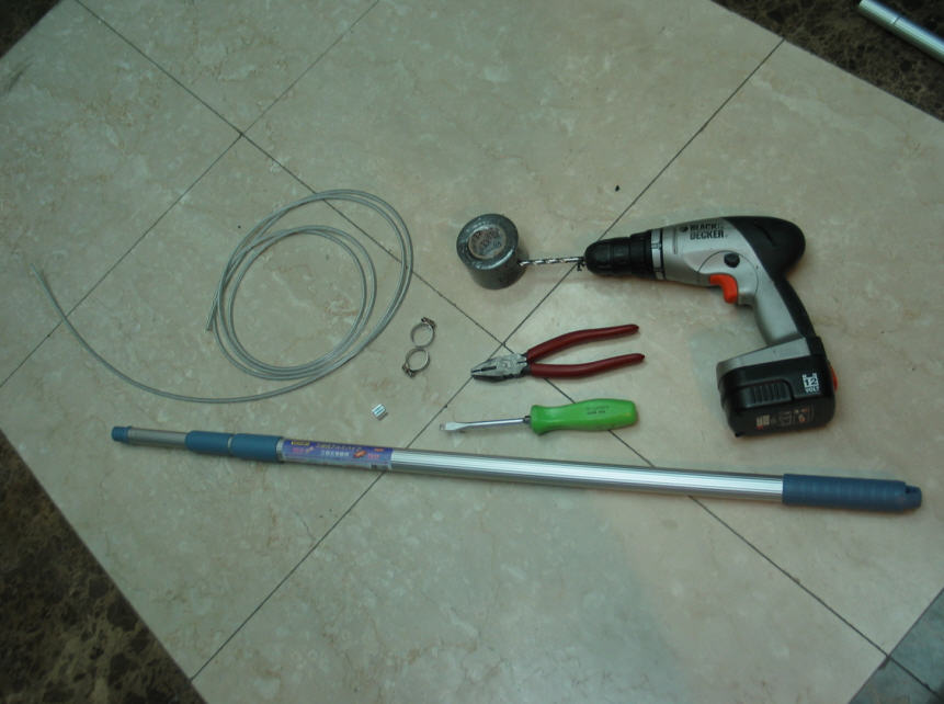
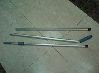
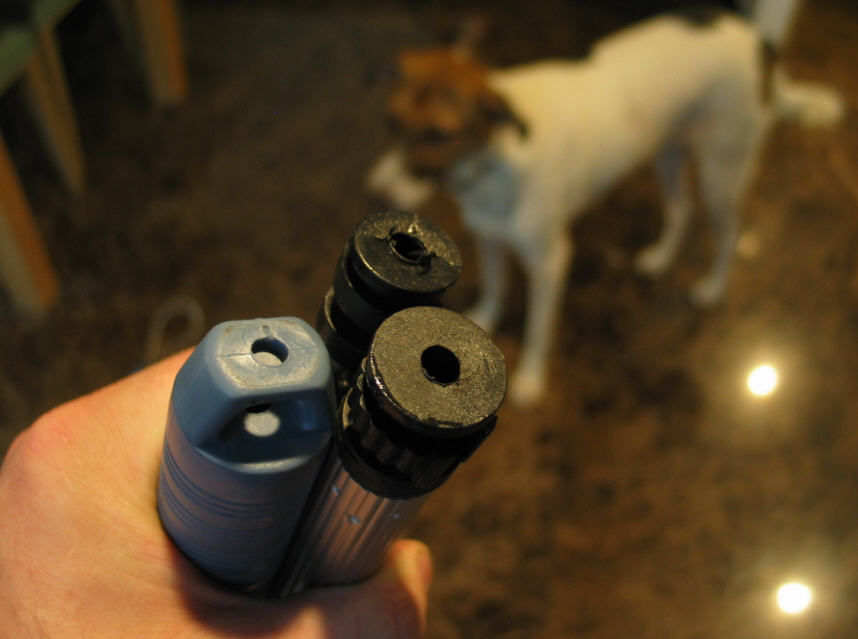
- Disassemble the pole enough to enable drilling of the locking mechanism. If it’s a 3-piece pole (as shown) the disassembly is a PITA and you have 2 mechanisms to drill thru. On the 3-piece poles, if you fully extend the pole and keep twisting the joint counter-clockwise while pulling really hard, the joint comes apart. Don’t twist clockwise as this will activate the lock and make it impossible. If it’s a 2-piece pole, then you’ll just need to take of the cap handle to do the drilling. Note: I choose 3-piece poles for the extra strength, and tape up the small extension, which is weak.
- Drill through the threaded end of the pole, the locking mechanisms and the end cap. Make sure the drill is perfectly aligned with the pole when drilling, especially for the locking mechanisms, which are quite thin where the drill penetrates.

- Thread the cable through all the pieces before re-assembly. It can be tricky to get the cable through the last hole, which is usually the threaded end when I do it. Usually, some jiggling around gets it in the hole after a few attempts. Make sure there is enough cable out each end for the dog loop and the hand loop.
- Reassemble the pole. For a 3-piece pole, it’s a matter of forcing the joints back together by twisting. For a 2-piece pole, it’s just a matter of putting on the cap handle again.
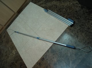
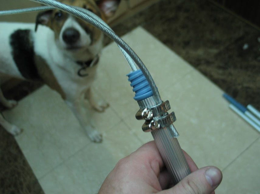
- Use the 2 hose clips to clamp the loose end of the cable as near to the thread end as possible. This will clamp onto the plastic end inside the tube for extra strength.
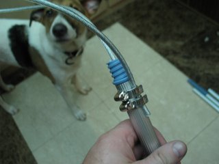
- Use the cable clips (or some plastic cable ties) to form a hand loop at the other end. This loop needs to be strong as once the pole is in use, this loop will support the full weight of the dogcatcher as he or she gets dragged along by a raging stray dog.
- Tidy up. Wrap the sharp edges of the hose clips with electrical tape. If you used plastic cable ties for the hand loop, it is worth wrapping these in tape also. When taping the hose clips, I also lock the small extension joint and tape it also, to prevent use and increase rigidity of the pole.

- Test. Extend the pole and lock the joints. There should be enough loop to fit over a dog’s head. To close the loop up it’s a matter of holding the pole with one hand an pulling the hand loop back. If the catching situation is hostile the pole itself can be let go and the dog can still be retained by holding onto the hand loop only. The Dog will naturally try to get away and the loop will tighten, giving the catcher time to regain control of the pole.




Guidlines about humane animal handling
Tomahawk Control Poles
Ketch-All animal control equipment
Alana Ecology Control Poles
Subscribe to:
Posts (Atom)
